Sante DICOM Viewer Pro
Work with the 3D windowThe program can create a 3D model from the 2D image data of the files of a DICOM series.The user can use the menu command File  Send Send The Active Series To 3D Window
to create a 3D model of the current series. The Active Series To 3D Window
to create a 3D model of the current series.The program offers 3 different 3D rendering techniques: The Isosurface technique, the Maximum Intensity Projection (MIP) technique, and the Transfer Function technique. The program can display the 3d model of one, two or all the three techniques simultaneously on the screen. 
The Isosurface techniqueThe program uses the marching cubes algorithm to construct the isosurface model, and allows the user to select the isovalue to create a model from different parts of the human body.A model with a middle isovalue: 
The same model with a low isovalue: 
In the upper-left corner of the isosurface window there is a slider control that allows the user to select the isovalue. 
The user can enable this technique with the menu command Show Isosurface Model (3D Model menu). The Maximum Intensity Projection (MIP) techniqueIn this technique the program projects in the visualization plane the voxels with maximum intensity that fall in the way of parallel rays traced from the viewpoint to the plane of projection.A model with the Maximum Intensity Projection (MIP) technique: 
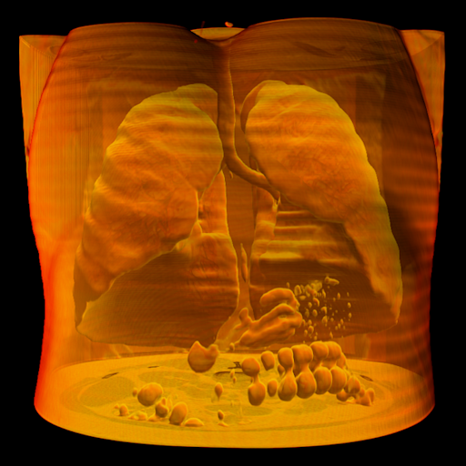
The user can enable this technique with the menu command Show MIP Model (3D Model menu). The Transfer Function techniqueThe Transfer Function technique is a volume ray casting and rendering technique that assigns a different color and a different opacity/transparency value in different ranges of intensity values. This is done with a histogram based function, the "transfer function". The transfer function consists several control points, and each one of them corresponds to an intensity value and it has an RGB color and an opacity/transparency value. The intensity value of a control point is displayed with its color and opacity/transparency value, and the intensity values between two control points are displayed with the interpolated colors and the interpolated opacity/transparency values of the two control points. With the use of the transfer function, the different parts of the human body are displayed with a different color and a different opacity/transparency value.
The user can enable this technique with the menu command Show Transfer Function Model (3D Model menu). The Transfer Function PaneThe user can design the transfer function with use of the Transfer Function Pane that allows the user to insert a control point in a specific intensity value, and to define the color and the opacity/transparency value of the control point. The Transfer Function Pane is accessible via the menu command "View Panes and Satus Bar Panes and Satus Bar Transfer Function Pane". Transfer Function Pane".In the background of the Transfer Function Pane there is the histogram of the image. The transfer function creates a palette of colors that is assigned to the intensity values and it is displayed in the bottom of the graph. 
Insert a control point: Hold down the Ctrl key of the keyboard and press the left mouse button on the desired point of the histogram. Change the position of a control point (intensity value): Press the left mouse button on the desired control point and move it left (in a lower intensity value) or right (in a higher intensity value). Change the position of a control point (opacity value): Press the left mouse button on the desired control point and move it down (for a lower opacity value) or up (in a higher opacity value). Change the color of a control point: Press the right mouse button on a control point and select the menu item "Change Color". Delete a control point: Press the right mouse button on a control point and select the menu item "Delete". Move a portion of the function: Hold down the Shift key of the keyboard, press the left mouse button on the desired control point and move it left and right. The changes are immediately displayed on the 3D model. Transfer Function Pane controlsThe program offers several predefined transfer functions as well as user functions that are accessible via the combo box "Transfer Function". Copy button Copy buttonUse this button to make a copy of the current transfer function. The user can make as many transfer functions as he/she wants.  Save button Save buttonUse this button to save the current transfer function. The user cannot save the predefined transfer functions, but he/she can make a copy of a predefined transfer function, modify it and save it with a different name.  Delete button Delete buttonUse this button to delete the current transfer function. The user cannot delete the predefined transfer functions.  Invert button Invert buttonUse this button to invert the colors of the current transfer function. Hold down the Ctrl key of the keyboard and press this button to invert the entire transfer function. "Transfer Function" combo box Allows the user to select one of the predefined or user-defined transfer functions. "Transparency Strength" slider control Adjusts the transparency of the model. The "Transparency Strength" is a part of the current transfer function and saved with it.
"Smoothness" slider control Adjusts the smoothness of the model. The "Smoothness" is a part of the current transfer function and saved with it. A low smoothness value creates a sharp model and a high smoothness value creates a smooth model.
The user can use the menu command 3D Model  Brightness to change the brightness of the model Brightness to change the brightness of the model
|
Copyright © 2024 Santesoft LTD, all rights reserved


 Download the application
 Sante DICOM Viewer Pro
 What's new in current version
 Order it now
 Ask for a written quote